Category: Project
Introduction – Apple Device Management
Managing Apple iDevices can be quite complicated and as the number of devices you are responsible for increases, the challenge becomes insermoutable.
This project is my attempt to get a Mobile Device Management solution running on a shoe-string budget.
Using only free or nealy free solutions, my aim is to take control of the devices i need to manage and understand how they are used, where they are and control the installation of both in-house and third-party applications.
Initially I intend to use only Apple provided tools. If this provides adequate control, then all will be fine and the project will end. If not, then I will investigate the miriad of other tools available, all be it at a significant budget increase.
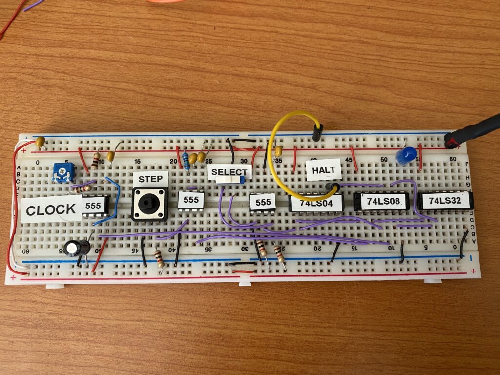
The Clock Module
The clock module synchronises the working inside the CPU. It triggers changes in state and timing of most if not all of the computer.
The clock module consists of 3x 555 Timer IC’s which are used to generate a timing pulse and also to de-bounce input from the user when taking single steps or changing the clock from run to step.
The variable resistor allows for variable clock speeds. The second and third 555 timers debounces the step input and the step/run select switch. Denouncing removes the tendency for the switch/button to “double tap” itself when the user triggers it. This happens in a fraction of a second which humans can’t see but computers are just that fast.
8-bit Computer
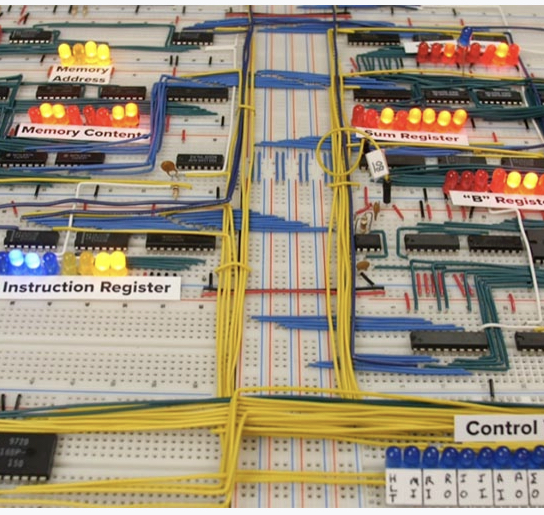
When I did my qualifications in computing in the 90’s, one of the basics I feel I missed out on was how computers work at an electronics level.
Recently I have been watching as series of videos on youtube by Ben Eater. This video series explains how a computer works on a fundamental level. Ben builds an 8-bit computer on breadboards.
This project is my investigations based on his work and is an attempt to make myself more aware of the underlying hardware I use everyday actually works..
Check out Ben’s videos on his Youtube Channel
Setup WIFI on Raspberry Pi
SSH into the Raspberry Pi over ethernet (see above).
Install the WPA wireless tools
sudo apt-get install wpasupplicant wireless-tools
Edit the networking file to use the wpa-supplicant file for wireless configuration:
sudo nano /etc/network/interfacesEnsure the wlan0 section uses the following lines:
allow-hotplug wlan0
iface wlan0 inet manual
wpa-roam /etc/wpa_supplicant/wpa_supplicant.conf
iface default inet dhcp
Optional: if static ip is desired replace “dhcp” above with “static” and add the following lines under it:
address 10.0.0.200 (my static address outside of the dhcp)
netmask 255.255.255.0
network 10.0.0.0
broadcast 10.0.0.255
Edit the wpa-supplicant file
sudo nano /etc/wpa_supplicant/wpa_supplicant.confEnsure that it has the following lines
ctrl_interface=DIR=/var/run/wpa_supplicant GROUP=netdev
update_config=1
network={
ssid=”YourSSID”
psk=”password”
key_mgmt=WPA-PSK
}
Save the file, disconnect the ethernet cable, and reboot the Raspberry Pi. It should now connect to the wireless network.
Fine Tuning the 3d Printer
Following advice from the SW Makers crew I gave up on the OEM software that came with my Felix and invested $150 in Simplify3d.
After working out the differences in the software. Simplify3d seems to be quite a good package and much more flexible that Repetier that is bundled with Felix 3.0
I had troubles after installing it on my Macbook Pro. It seems that the default baud rate for the USB on the Fellix three is too fast for the Macbook and Steve showed me how to adjust it at last weekends Nerd Herd at SW Makers.
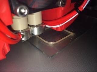
One useful important thing to remember is to removed the head away from the project after the print to ensure the model is not spooled by “oose” from the extruder after the print is finished. Thanks to Paul for digging up the information on the Gcode to move the head away after the print is finish. He has posted it here, I’ll quote it below for posterity.
The Starting Routine:
G90 ; Absolute positioning
G28 ; Move to origin – go home
G1 Z10.0 F3000 ; Controlled move – take bed down 10mm
G1 Y180.0 F3000 ; Controlled move – bring head to near front of bed
G92 E0 ; Set position
G1 E20 F200 ; Controlled move – extrude 20mm of filament
G92 E0 ; Set position
G1 Y0.0 F3000 ; Controlled move – move head home
G1 Z0.0 F3000 ; Controlled move – take Z homeThe Ending Routine:
M113 S0.0 ; Set extruder PWM
G91 ; Relative positioning
G92 E0 ; Set position
G1 E-5 F2000 ; Controlled move – retract filament to stop the ooze
G1 Z10 F1200 ; take the bed down 10 mm, so as to clear the printed part
G90 ; Absolute positioning
G1 X5.0 Y5.0 F3000.0 ; Controlled move – move head to 5, 5
M84 ; Disable motors
M107 ; Fan off
M104 S0 ; Set extruder temperature to 0 deg C
M140 S0 ; Set heated bed temperature to 0 deg C
Once Steve showed me how to set the software up and we checked the printer using a “thin wall” calibration test, I was able to create models with much greater strength that looked much more like what I’ve seen online.
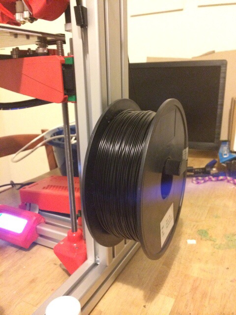
So much stronger that I was able to print a Spool Holder for the side of my Felix. This is not the most popular holder among the 3d printers but I kind of like the way the friction brakes the spool from allowing the filament to de-spool (is that the correct term?)

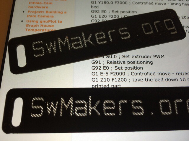
As part of our presence at the SW Science Spectacular in August, we had printing a bag of “swag” for the muggles to grab as they pass our booth. Steve made up an STL luggage rage with our website on it. We hope this and our increase printer family might generate some more interest in the club and maybe even a new member or two. (PS: if you haven’t been to it yet, head over to www.swmakers.org and check out the news)
3D Printing
It finally arrived. I’m now the proud owner of a Felix 3.0 dual extruder 3D Printer. After a few SW Makers Meetings where I had to watch the printing happening I thought I’d buy myself a 40th birthday present.
I splashed out and added most of the extras, dual extruders, LCD panel and I made sure it was in Ferrari Red so it goes faster.

After almost 5 nights of building and testing, I finally got it together and worked out all the kinks in the system. (Yes, that’s code for “I put it together and wired it wrong a couple of times”, it is a learning process after all.
The first ever print from the machine (besides those I consider testing, that didn’t even stick to the print bed) was a calibration block. It prints a super thin walled rectangle to test the reliability and adjustment of the printer. I think it worked out well.
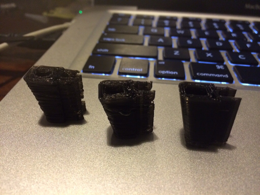
I then moved onto the tool holder. It’s a small block which clips onto the frame of the printer and holds a set of tweezers used to clean away excess filament while printing. It took 3 prints but I finally managed to get a good print from it.
Apparently I’ve got a lot to learn about 3D printing but hopefully it won’t be too long before I’ll move onto making some really cool parts for other projects around the cave.
Coke Can Stove
 Timing: An afternoon creation.
Difficulty: Easy
Cost: Almost nothing
Tools:
- scrissors,
- drill press, 2mm drill bit
- ruler
- plyers
Materials:
- at least 2 375ml “coke” cans,
- Methylated Spirits for testing.
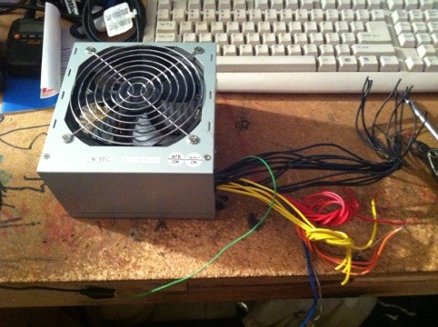
Project – Bench Power Supply
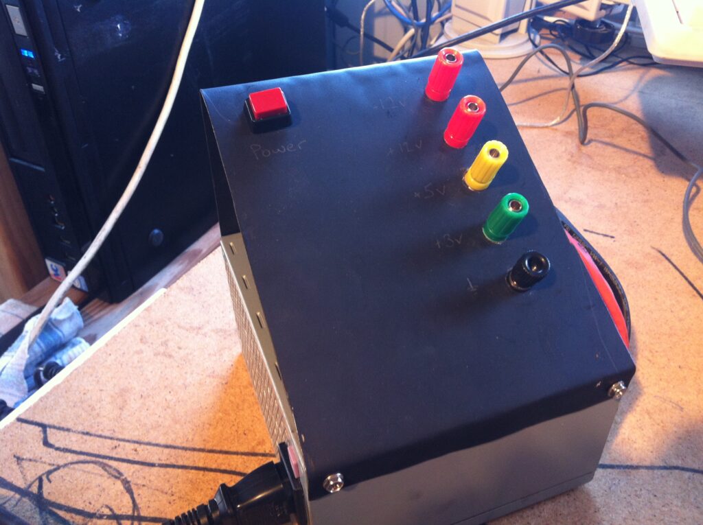
One thing that every man’s cave needs is a power supply. I already have a 12volt regulated power supply but my interest in micro-controllers makes it ncessary to have other voltages available.
Enter the ATX power supply. The ATX power supply is found in most recent computers and many a time I’ve thrown them out in my work. I decided that the power supply from one of my old machines looked too new to junk and so I began the Bench Power Supply.
There are many instructables and how-to’s on the net which outline the process of modifying your power supply for use with other projects.
The simplest of these is to use the voltages output by the PSU without any modifications. This was my choice for this power supply project.